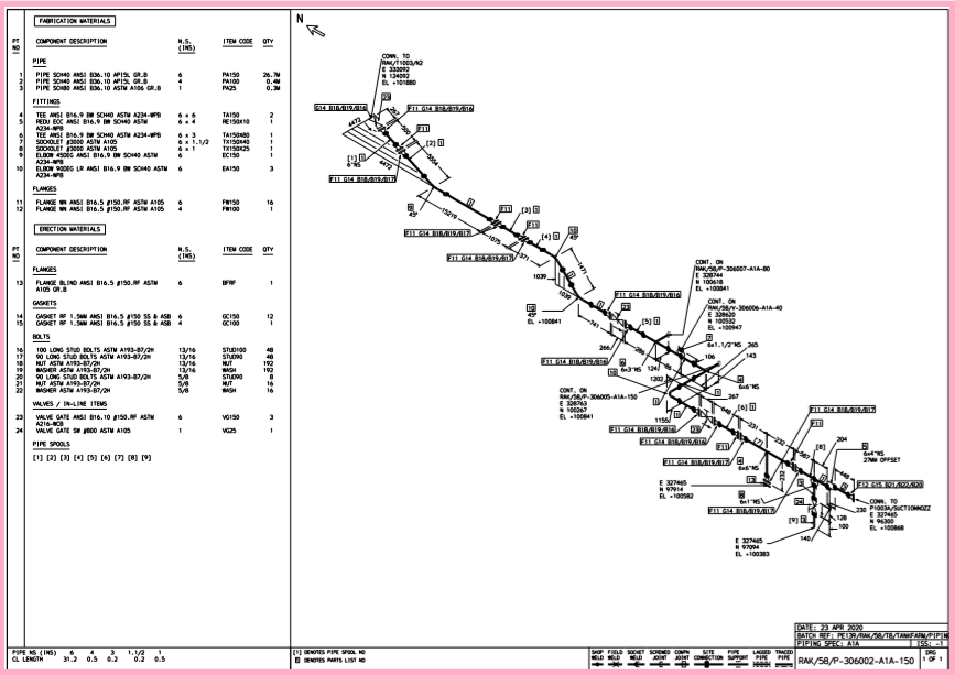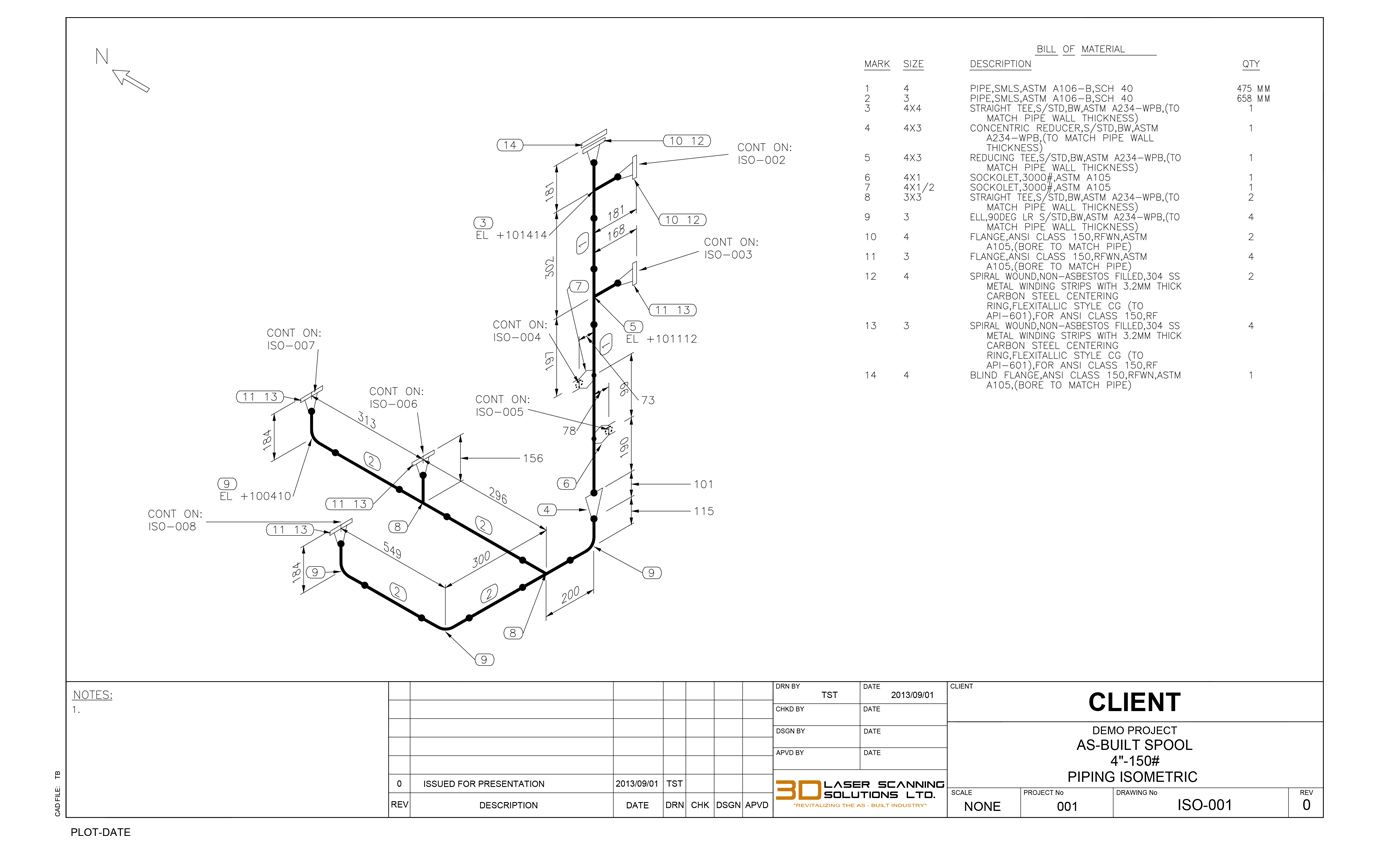


The bold black dots denote the butt welds. Now if you notice the isometric drawing you will see that the isometric view is similar to the orthographic view where the red lines are for the pipes. The dimension A and C is from the front till the centerline of the elbow.B is measured from the centerline of one part and the centerline of the other part. The image is an orthographic drawing of the butt welded pipe. Let us see how the isometric piping draw is read differently from the orthographic drawing. In the figure below you will see both the isometric and orthographic view. Make sure you note the above mentioned points before going ahead to draw isometric drawings by hand. Let us explore the basics about how to draw isometric piping drawings by hand. How to draw Isometric Piping Drawings by hand? The flanges or coupling connections will be defined in the Bill of Material section. There is a note that will explain the type of connections to be used in that place.A single thick line denotes connections that are detachable. All connections have to be denoted by a bold dot in the piping draw.

It also helps understand the elevations and depression directions properly ConnectionsĬonnections made using welding, soldering or gluing have to be shown on the isometric drawing. The north arrow is drawn to denote the direction in which the pipes in the piping system run. The simple trigonometry and pythagoras theorem is used to determine the pipe length with the offset. In case a 45 degree elbow or an old nozzle is used in such cases the piping offset is used. Offset is present in the design when a pipe with move in an angle other than 90 degree. Here are a few things to keep in mind about how to draw isometric piping and how to read isometric piping. The outer fittings are not considered for measuring. Isometric piping draw represent the centerline of the pipe.The dimensions are measured from the centerline of the pipe.


 0 kommentar(er)
